
norrs
-
Posts
448 -
Joined
-
Last visited
-
Days Won
6
Content Type
Profiles
Forums
Gallery
Events
Store
Everything posted by norrs
-
I just started reading this tread from the beginning. I got to the second page and choked on my breakfast! I totally had an immature bevis and butthead moment. Yes I know what he meant but it was the way he said it.
-

Hi Guys And Girls In Darwin Vicinity Xr6T
norrs replied to bens-xr6t's topic in Western & Northern Australia (WA, NT)
Hi Matt. Welcome to Darwin. You have arrived at the right time weather wise. Our cars hate the heat! -
Install tapatalk on your mobile then just take the photo while in the middle of your post and upload no worries. I don't seem to have a limit on the size. I think tapatalk hosts it or something. Anyway what old mate says seems to make more sense from what I now understand of how the system is supposed to work. It sounds like the Pcv inlet needs fresh air like one venting to atmo on top, while the outlet Pcv sounds like it should be a non vented can so it still can generate vacuum from the intake manifold. So two cans I found this nice explanation on a US forum: quote----------------- Your pcv system is designed to use the pressure differance between the atmosphere and your intake manifold to vent your crankcase. The pcv outlet into the intake manifold is low pressure (vacuum), and the pcv inlet in the air box is high pressure (atmospheric pressure). The difference in pressure forces air to flow in through the inlet (air box) and into your crankcase, the blow by gases are sucked out of the crankcase through the outlet (intake manifold). Even with the stock setup, the pcv system will not function well under hard acceleration. This is for two reasons, the first is that more blow by gases will be generated as you accelerate. The second is, that when you fully open the throttle, you tend to loose the vacuum in the intake manifold. But because of the air filter restriction, there will still be some flow in your pcv system, but sometimes not enough. Now look what the air intakes you have described have done to make a bad situation even worse. In order to be compliant with pollution regulations, they have moved the pcv inlet from the airbox (whch they don't have), to the intake tube. Now when you accelerate hard and fully open the throttle, the pressure will equalize between the intake manifold and the intake tube, until you have enough rpms that the throttle body becomes a significant air restriction. So for most of the time with these intakes under hard acceleration, there is no pressure differential between the pcv inlet (intake tube) and the pcv outlet (intake manifold), and hence no air flow in your pcv system. So the blow by gases build up in your crankcase and have to vent out. The blow by gases will find the path of least resistance, which will more than likley be back out the pcv inlet. When you don't have an airbox with your intake, the solution of replacing the stock pcv inlet with a filter on the valve cover works. This still maintains the air pressure differance between the pcv outlet (intake manifold) and the pcv inlet (the filter to the atmosphere). So your pcv system will continue to work like the stock system. The only catch is that you will no longer be compliant with pollution regulations. For pollution reasons, the inlet is supposed to placed so that any blow by gases that do backflow out of it, are sucked back into to the intake to be consumed by the engine (hence the placement in the airbox). The reason for the filter on the pcv inlet, is to filter out dust and other large particles, so they don't get sucked into your engine.
-
Thanks So what's the purpose of the pcv and does the catch can still serve that purpose. Should the line from the intake manifold to the catch can have a check valve/pcv in it to stop boost leaking
-
That's a bit small isn't it. I've been reading up on cans (here and other forums) for a while now and the more I read the more confused I get. There seem to be arguments that it won't work if vented to atmo as it requires vacuum to suck out the gases. Others are saying this is not true. Others say if you don't plumb it back there are idle issues. Can someone have a crack at explaining how the oem system works. Which direction does the air flow through the two ports on the rocker cover. I assumed that fresh air comes in through the front one, but it's dumping oil in my crossover pipe so it obviously heads the other way sometimes (is that blowby). Wouldn't a valve correct this or inline filter? What's the purpose of the valve on the rear one, some people appear to remove it and just plumb straight to the can. A dumbed down explanation will help me decide on my setup.
-
Aftermarket Fuel Filters...what I Did!
norrs replied to IH8TOADS's topic in Engine Management & Fuel Systems
What he said. What is the flow rate? -
Car Cranks But Takes Long Time To Start
norrs replied to boost69's topic in Engine Management & Fuel Systems
mine was doing the same and then I installed a check valve on my fuel pump outlet and the problem was fixed. -
Oh bugger on the fg it appears to have different colour wires. a pink green wire (thicker positive) and a white wire (thinner negative). My guess is that the pulse wire is the white negative like the injectors
-
yes, that is excellent advice. Thanks.
-
Thanks Ralph. I wonder what is the best way to test if it is working. My failsafe engages if the system is turned off but how do I tell if the wastegate is open. I have a boost guage, I suppose I just see if I can't make boost when it is turned off. This system I have also allows it to protect against the engine light coming on when the failsafe opens the wastegate. When it's up and going I'll probably leave the CEL light to come on as it would be a good warning that the failsafe has been triggered to show there is a problem. I should be able to clear the CEL with my hand controller I assume Well in other news my tuner had the car today but we had to cancel till next week. But he did say that he has meth/water injection on his other cars and is familiar with how they work. He will do some testing with before and after so we can see the results. Now I just need meth. Darwin has run out for over a week now
-
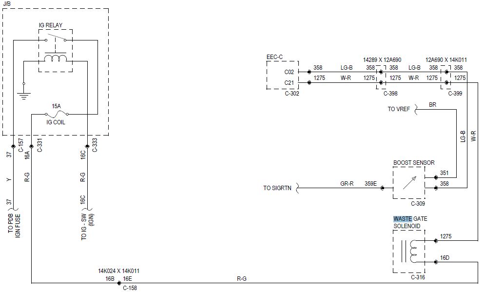
Ok looking at this wiring diagram for a BF (mine is FG) I guess the pulse wire for the waste gate solenoid is White and red. Ie if this wire is disconnected then the wastegate would open to purge the boost.
-
Ok I'll ask this question here but if I get no takers I may have to start a topic again. I need to set up the failsafe now. On a flash system it appears that my only option is to bleed boost if the meth fails. I assume that our wastegate solenoid is really just an electric boost solenoid run by the ecu. From what I can gather the system I have has an inbuilt relay that opens and closes the connection if there are injection issues. Basically you cut the pulse wire to the solenoid and run it through the system. Anyway what I need to know is if anyone knows the colour of the correct pulse wire for the wastegate solenoid. And I welcome any comments about whether any of my lay assumptions are incorrect.
-
Yeah I'm booked in this Friday for peckys. He is the only real local tuner. I'll go with him then. I was considering SAS because I heard he had worked with water meth injection and would have gone with him if there were great reviews but there doesn't seem to be. The benefits of the local tuner seem to prevail here.
-
I believe they are also known as SAS
-
Hi guys. There is a guy from Silverwater automotive (NSW) coming to Darwin next week to do some tuning. I was booked in to a local tuner but now I'm considering cancelling and going with this NSW guy. The Darwin tuner (yes there is pretty much only one) doesn't get much time on our cars. He mainly gets holdens. Unfortunately I can't find many useful and current reviews on here about Silverwater automotive. Has anyone used them ? What's their reputation like.
-
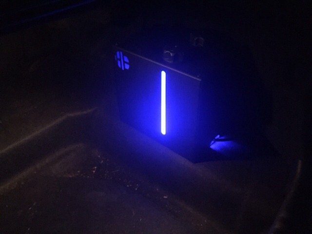
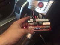
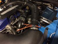
Ok. Mofos, I've finished the install. I just need a tune now. I only have water in it for now. Will buy some methanol Monday then take it to tuner. Aquamist is a complicated install and I'm yet to do the failsafes, that it even more complicated. I'm not sure about running it before I take it to my tuner, even though I'm on a lean tune right now and it may benefit from the water on full boost. My tuner said my current tune is too lean, so it may actually be safer with the water on. I'll do a write up on a different thread on the install. But here is a teaser: Yes I have some tidying up to do but it is getting there. Sent from my iPad using Tapatalk HD
-
Ok thanks guys.
-
So as far as which one pulses is it the negative that pulses?
-
Ok guys which one of the injector wires is the negative pulse and which one is the positive. One is large white wire with red stripe and the other is white

-
ok so continuing on from my question above, I had the aquamist guy confirm the wiring for the ecu wire. he said He also said that the blue wire was optional as a trigger for the system to start at a boost point rather then a IDC point (42% by default). Then it sprays according to IDC after that anyway. I see no benefit with having it start from a boost reference rather then IDC reference so I might skip that. What do you guys think? So regarding the injector wire (green) do we have resister pack on our injectors and if not, which colour is the negative (pulse) wire? Regarding the red wire, I assume I can just connect it to any ACC wire because I assume that is when the ECU starts up. I'd like to avoid splicing into any further injector wires if I can help it. What do you guys think?
-
Can you post a pic of your setup Sent from my iPad using Tapatalk HD
-
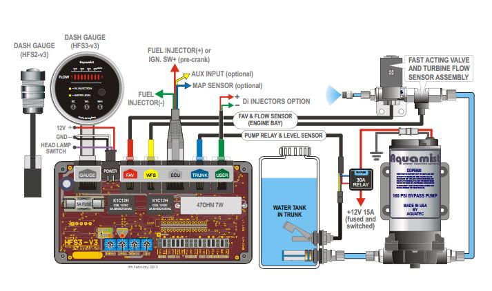
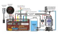
Ok I'm up to the bit where I splice into the injector. here is the diagram: So where do you reckon the best place is to link into the injector pulse wire. Is it off ecu or piggyback of back of one of the injectors. Manual is here for full info http://www.aquamist.co.uk/HFS3/manual/HFS3-v3.0w.pdf
-
Thanks guys
-
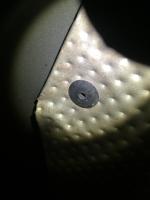
I want to bolt something into the floor of the drivers side of my boot. But the heat shield would need to be removed to access the nuts. It seems to be held in place with these rivet things So what's the go. How do I remove them and reinstall them. They look like they would need to be drilled out and then Popriveted back in. But I assume that they are plastic Rivets to stop vibrations

-
Yeah I was thinking the same thing. They seem to have done some good work on the computer side of it but it isn't functional and it looks crap!