

ken666
-
Posts
140 -
Joined
-
Last visited
Content Type
Profiles
Forums
Gallery
Events
Store
Articles
Media Demo
Posts posted by ken666
-
-
They do if you split each tab before fitting it, thanks for that.
I spoke with a mate who's been a mechanic for 40+ years that specialises in custom modifications with the same concerns, he said it doesn't need something to hold pressure on the bolts but rather just a physical stop to prevent progressive unscrewing of the bolts.
Apparently the forward and backward load and stretch of all the parts involved is the cause of habitual loosening of the bolts, but with a physical stop...
Problem solved 😬
Hopefully! I'll definitely let you guys know if it fails 🙂
-
Locking plate ordered, for $35 including postage!
I wouldn't fit a flywheel without one at that price, I had to pull the box 3 times in a few months just to retorque the flywheel bolts last build...
Got sick of that quick!
-
I like the tabs and the ease of using them
Simple remedy, probably more reliable than getting the holes drilled in the exact direction without first torquing to spec then removing and drilling (if you have a press...)
Tabs can be manipulated to where you need them, ensuring things don't loosen of at all.
Thanks for your thoughts and knowledge
Ken
-
Nice, yeah I'm lazy at this end of the build!
I will order a set immediately.
I want to enjoy driving the car now, the build took almost 3 years..
It's depressing having a nice car that you can't drive
-
Hey guys, is there any other way to keep the bolts that hold the flywheel to crank tight.... without coming loose time after time?
I've tried using a couple of different grade Loctite thread lockers (243, 263 and another brand of purple super duty) but everytime I put a socket on the bolts, I find that they are either loose or not quite as tight as they were torqued to.
I'm using ARP 2000 series bolts and I have followed the manufacturer instructions to the tee.
I know of people who actually put a tack weld on them and swear by it, but it's a little messy IMO, and would have to affect the balance of the motor (considering I spent a fortune on having everything balanced within a gram)..
Please let me in on your secret, if you have one!
Cheers Ken
-
Yeah well that's the last thing I need, cos I already lose some flow/pressure through the little end oiling.
That's why I uprated the pressure to 60psi, I know that it works the pump gears harder, but everything has been upgraded to ensure reliability.
I will definitely calibrate it by actual pressure at the flange.
-
Nah, it's a ceramic ball bearing core.
Haha, now what you have stated comes back to my original theory.... ok, not to the depth of journal vs ball bearing requirements!
But I didn't need to consider the other.
I've always associated oil restrictors with the purpose of regulating unnecessary flow to solid lifters and camshaft oiling.
It's always been the first thing to do on a motor that has excessively large big end or main bearings. (Cleveland V8's), by regulating the flow to the cam and top end you can safely lubricate the bottom end without fitting a high volume pump which would eventually lead to a failure due to the added load on the distributor gear and pump drive...
Thanks for the feedback, thought I learnt something new today...
Only to have it spoiled!
-
Pressure and flow are always relative, but there's too many variables to consider when upgrading something that depends on the system to survive!
That's why I studied and asked others for advice.
I've got a spare flange sitting here, I'll just connect it to a mechanical gauge and follow some formulas that I have found to calibrate it to suit the oil and system.
Obviously I will oil the turbo from a junction from the oil cooler system while making the necessary adjustments.
Thank for your thoughts
Ken
-
Cheers mate, I was doing some more research right now and have learnt a lot about the oiling and pressure requirements for different types of turbos!
It appears that the orifice in the flange may be intentionally left the size it was drilled so that it can be opened up to the necessary size to achieve the required pressure after it..
I was under the impression that the restrictor was used to regulate the volume flow of oil, not to regulate the pressure of the oil.
That's why I thought the drain line had to be upgraded so significantly?

-
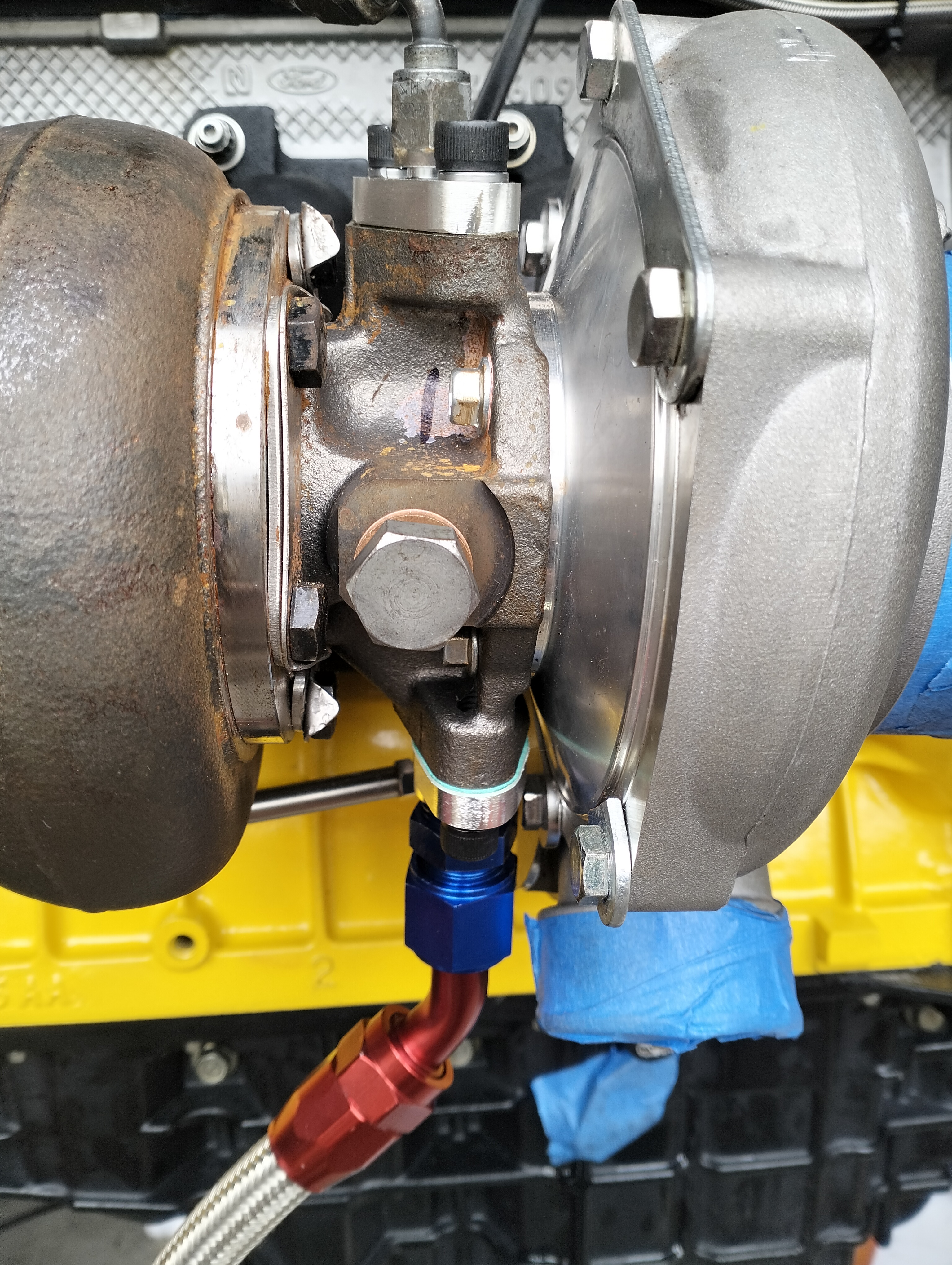
Hey guys
I'm fitted new oil feed and drain lines and filter on my GTW3884, after having my sump modified to run a 19mm drain line, I went to screw the oil feed line to the turbo but it has a flange fitting instead of the standard nipple fitting.
The flange that was supplied with the line kit has a 2mm restrictor orifice, should I open this up or leave it as is?
When I bought the turbo I asked if I need to fit a restrictor and was told not to worry about it.
However I was going to be running standard oil pressure at the time, but now I have upgraded to 60psi with the oil pump.
What do you think?
I'm a bit concerned that I could starve the turbo of oil.
-
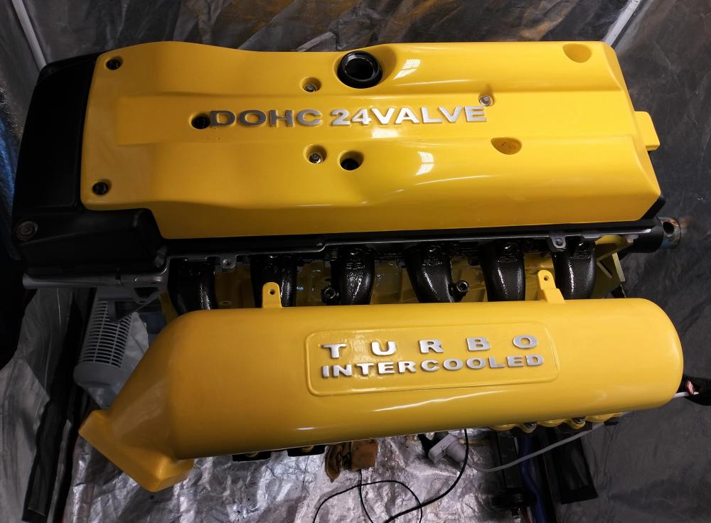
As I posted recently, I'm almost done building the new powerplant for my mk11 BA turbo.
I know how a junkie must feel when they know they are close to a fix!!
It's taken me almost 2 years to come to this stage of the build (COVID, and other unplanned delays from weekly income)
But I recently had a push via living circumstances and having to relocate.
Which left me with little choice but to at least seal the bottom end for transport etc, so I took 3 weeks from work to tend to first my youngest daughter requiring surgery (yesterday, which was a great success. Thanks for your comments in advance.)
Then my eldest daughter giving birth to my first grandchild either tomorrow or Friday, and then finding time to finish the build while relocating in the spare time I find!!!
What are your thoughts on my colour scheme for the new powerplant?
-
 3
3
-
-
A lesson for you "do your own work" at home gurus out there...
Always flexigauge every bearing for peace of mind when putting all those expensive goodies together.
I was dumbfounded when I went to buy it for the build, repco didn't stock it anymore, super cheap staff didn't even know what it is and 2 of the 3 local engine reconditioning shops I visited don't use it anymore?
I eventually found an old fella in a mechanical repairs shop that had literally a box of it!
-
1
-
-
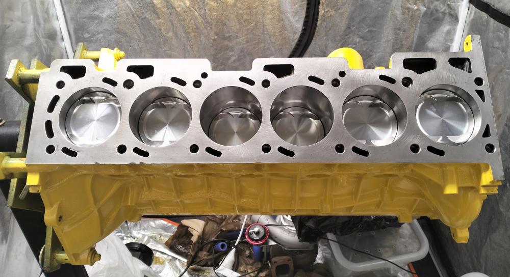
The thing that made me feel very much happiness today was the moment when I checked my bearing clearances after already building the bottom end once, but when doing the final check of the clearances on the mains, I found that the machinist may have misunderstood what the motor is actually being built for... Street!
He closed and line honed and undersized the crank to a clearance of .0032".
Reckons that's how he builds super high boost strip cars like that to compensate for crank flex so they don't burn the oil onto the bearing shells!
I asked him how do I go about oil pressure once it warms up, he said drag cars rarely get too warm!
Then it clicked, ohh are you putting that in a street car?
The thing that made me feel happy was learning that he can get undersize in one thou increments, so I only had to change the shells🧐
-
That was the original plan!
Probably the best one too.
-
That's very interesting, thanks heaps for this.
I will give it a go tomorrow, Im glad that's all it is I have a puller unit that is almost identical to the one in the link so it won't be difficult at all
-
Hey guys
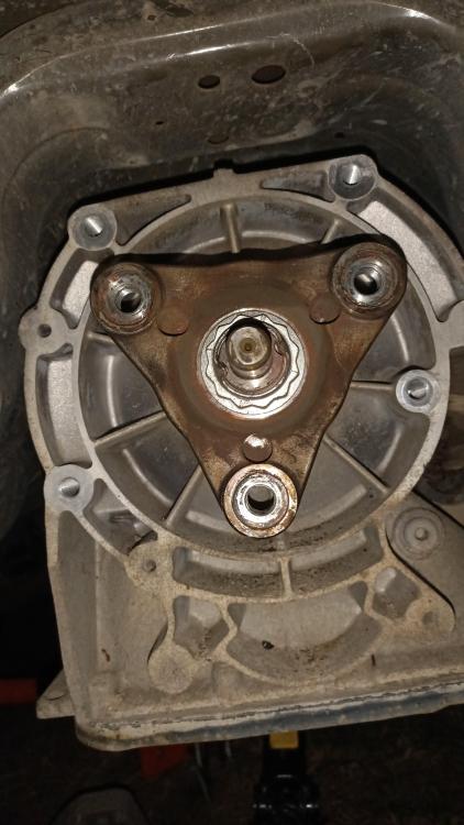
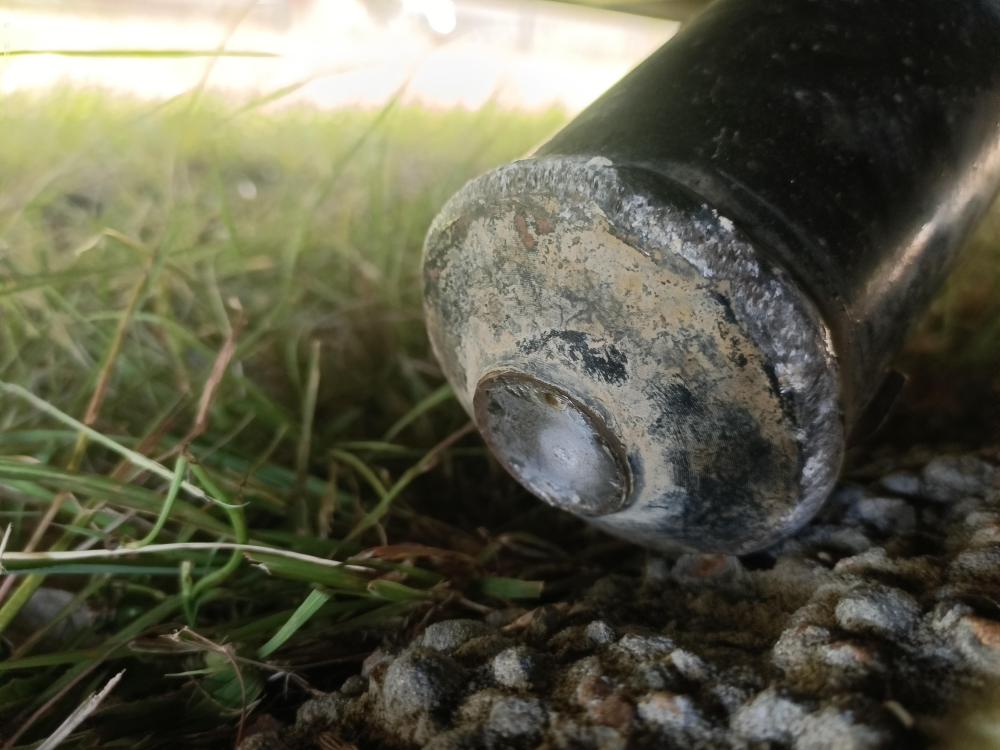
Has anyone else experienced a slip yolk stuck in the back of a zf 6 speed auto?
I broke the rear shaft where the spline goes into the cv joint on the rear a few days ago and attempted to remove it on the side of the road during the week, and after two separate attempts with bigger and better tools I still was unsuccessful in getting the yolk to pull out of the box.
I ended up having it towed home and I put the rear of the car up on ramps and continued to remove the shaft from the yolk and the gearbox mount bracket etc to give me a clear view of the extension housing and yolk.
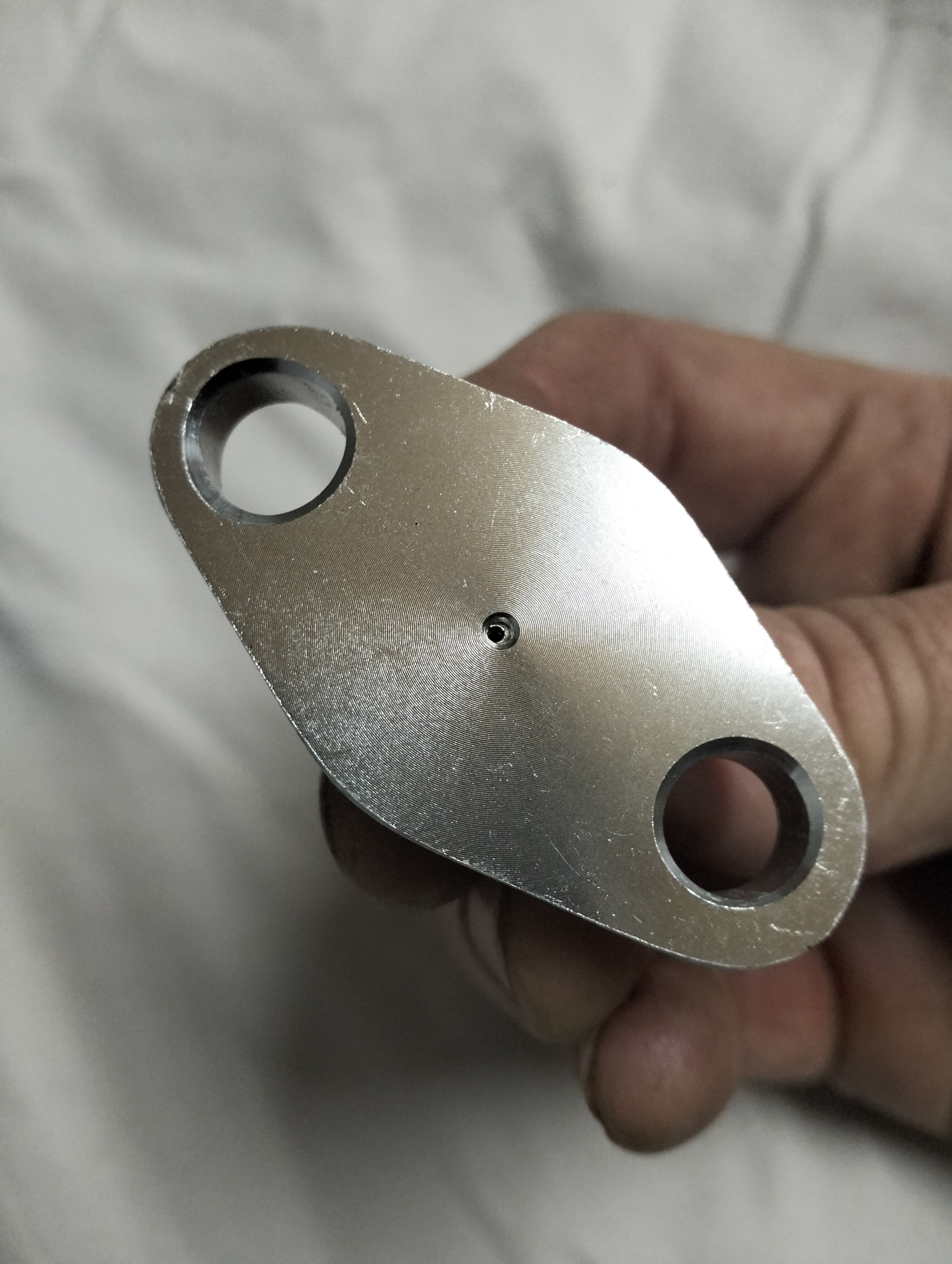
I have attempted to pull it out by making a plate that bolts to the yolk and has a pull lug in the centre, then attached a 1.5 tonne chain block to the diff cradle and hooked up the chain and began to load up the chain.
I then used a copper hammer to tap the yolk from the sides, back and even forward to give a sudden shock whilst weight was on the yolk.
But never had any movement whatsoever, so I loaded the chain up until the chain block started to load up to its limits...
Still no movement, and I'm now doing some last minute checks before beginning the assembly of the replacement shaft and bearing etc and bolting it all to the yolk that's stuck in there.
I can't see it causing any problems, as the shaft needs minimal end float due to the driveline being fixed and fitted with IRS.
I think there is enough end float in the shaft to CV on the diff end.
Any ideas would be great, maybe it's happened to someone here cos my mechanic mate is stumped and has never experienced this in 25 years in the business.
Cheers Ken
-
I have a rip shift, it's really good and tight with nice gate definition.
Just be careful not to set the overthrow stops correctly, especially for the shifts on the pull of the shifter (2nd, 4th and 6th gears)
otherwise you will destroy the synchro rings and possibly the selector mechanism...
I did in the original box, but was told about this before setting up the new box.
-
I experimented with different types and compounds of pads a couple of years ago and I was extremely impressed with the final combination that was suggested to me by a suspension guru.
I used the same rotors on front and rear as you have, but after trying several "top shelf" big name brands (and lots of dust and mess, along with chewing rotors out due to the soft compounds)
I fitted QFM (Queensland friction materials brand) standard replacement pads in conjunction with good quality aftermarket braided lines all round and high performance brake fluid (still with the ventilated discs)
I could stand on the brakes from ridiculous speeds, and not experience brake fade due to overheating.
I forgot about how much that improved the stopping power of my XR8 until I read your post, and I swore that I would tell as many people who would benefit from such small changes with the right parts.
Enjoy
-
Hey guys I'm chasing a cover that's not broken!
Don't need to upgrade, I'm only fitting it into my FG xr6 n/a.
I've got stuffed bushes and noise in the original cradle and diff, and have a complete rebuilt ba xr8 assy sitting in my way in the shed.
I got lots of 2005 xr8 spares if you are looking for anything in particular.
Cheers Ken
-
Can anyone help me with the pro's and cons for loctiting the main studs in on my current build?
I have upgraded the bottom end to 14mm, fitted a 13mm thick custom made girdle and hand finished all the stud holes into the block to exact depths required with a modified finishing tap so once I drop a 3/8" stainless ball bearing beneath each stud I have exactly 2mm clearance to the modified sump.
However ARP recommend to only hand tighten the studs before torquing up the nut, unless the studs are going to be left in the block.
Then in this case they can be locked in with Loctite....
My question is, how tight should they be torqued to, and what compound is going to be appropriate?
I would expect that 243 should be sufficient, with torque around the best one can achieve with a normal length allen key??
Once the nut is torqued the stud should be quite firm in the block.. but I don't know!!
Any ideas or experience with this fellas?
Cheers Ken
-
Yeah I ended up leaving them on, as the girdle is 13mm thick and I have fitted 14mm studs in the caps (which I overlooked getting drilled out to suit!)
In the end I've decided to fit a modified sump to combat the clearance issues and even cut a piece of another windage tray to fit on the last 3 caps too.
Thanks for clearing that up Puffwagon
Cheers ken
-
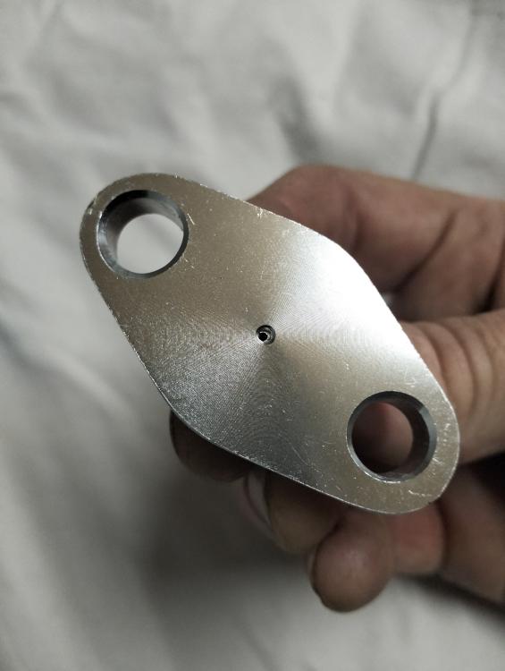
8 hours ago, Puffwagon said:
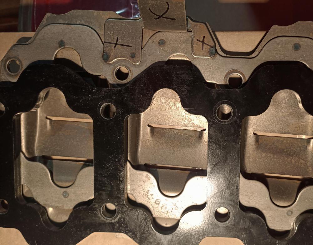
I removed the windage tray from its side supports by drilling the spot welds, and fitted it between the girdle and the arp fasteners on the main studs.
Here's a pic if anyone else is interested in the side mount that it could on as Puffwagon has removed in order to allow the windage tray to line up with the studs properly.
-
Yeah I won't be assembling the engine without it that's for sure.
When I used to build Cleveland V8's that was the first part that I would source for the build, especially when it was going to have big G's under acceleration!
Nothing worse than starving an engine of oil even for a millisecond.
-
Cheers for that, I expected that I wasn't the only person to feel the benefits of fitting it.
I expect there is going to be slight modifications to install both, there appears to be a slight modification (either drill it out, or weld on a new larger diameter washer) to fit the oil pump pickup on the stud anyway.


VCT actuators... are the pre 2004 & the post compatible?
in General Tech
Posted
I'm doing a head swap on a friend's ba N/A xr6 and it appears that the reco head he has sourced to do the job is a 2003 head and has the smaller diameter vct actuators, where the car to get the swap is a mk11 with the bigger sized versions.
The replacement head is fully reconditioned and I was wondering if it's possible to fit the replacement head along with a pair of actuators from the donor car in which we sourced the head before reconditioning?
I'm not too familiar with how they function but I'm assuming that it's basically a solenoid valve controlled by the ECU to control the phasers?
My question really is, do they have the same flow rates as the later model or will they need calibrating in the ECU?