fab83
-
Posts
5 -
Joined
-
Last visited
Recent Profile Visitors
708 profile views

-
Hi all, for those interested I hooked up the tubing so have the boost gauge actually working now, was easier than I thought. The tubing that came with it was going to be so I went to bunnings at got a 5m roll of 5mm clear tubing (used approx 3m), cost a few bucks, it was a little bigger than what came with it but still did the job. Firstly, I have a custom head unit installed where the old 12v supply is down the bottom (see photos at the top) behind my head unit there is an opening where I could push the tubing through about 20cm, then looking from where the foot pedals are in behind the ICC at the bottom you should see the tubing come through the back, you should then be able to pull all the tubing through to where the foot pedals are. Then just above the foot pedals there is a rubber grommet with some wires already going through the firewall, this is where the tubing will go through. The tricky bit for me was getting the tube through the rubber grommet, because my thick amp wires already come through there too, the trick was to push something hard at least 5cm long and 5mm width into the end of the tube (I used a bit of plastic off a toy I found. Something the width of a screwdriver would be ideal though unless you want to break a screwdriver youll have to find something else), it will provide extra strength and you should then be able to push the tube through without the pipe buckling. The T-piece supplied fitted nicely on the small pipe coming off the blow off valve. A couple of zip ties were used to tie the tube up neatly under the bonnet. From where the pipe entered below the ICC near the 12V supply you will have to feed the rest of the pipe up behind the ICC by pulling the ICC forward. The tricky thing was putting the ICC back forward again because there is not much room for the pipe, I had to weave it around to the left of the air con ducts then upto the gauge, its a snug fit but seemed to work ok (under the gauge mount there was a hole that went back towards the engine and headed down, perhaps this is another way for the tubing to go, I tried pushing the pipe down there to see where it goes, but no luck. Can anyone shed some light on that??). I then simply attached the tube to the gauge and used some sealer and a zip tie to ensure it was a good fit. Works great.
-
Hi all, I recently bought some pioneer 6x9 rear speakers for my turbo. Unfortunately I didnt do my research, not realising that the standard rears are 5x7's, until coming back and looking on this forum. Now there are alot of guys on here who so its silly to install 6x9's because a sub is all you need for your base, and 5x7's can deliver enough sound to go with that base, though considering I already bought these speakers I thought id go ahead and install them anyway. So installing 6x9's can be done, all you will need is a set of 40mm speaker spacers, a drill, and some 75mm screws, and other miscellaneous bits. The speaker spacers are obviously to avoid cutting into your parcel shelf to increase the size of the speaker whole. The first step was to remove the top rear shelf behind the rear seats (by removing a series of easy pull out clips. You will have to push both rear seats forward, there are two clips back near the rear window, 2 clips behind the rear seats, and one in the middle in top of the shelf), then the factory speaker covers can be removed. There is a big chunk of carpet/material that should be cut away from each speaker hole, because it gets in the way. Once the speaker covers, and the chunk of material has been cut off, the top rear shelf can then be put back on. The next step is to remove the current speakers and install the speaker spacers. This was the hardest bit of all, because you had to line up from the top where the spacers should go, though the only way to drill through the shelf is from below, so there is a bit of guess work. There may be better ways but the way I did it was to get in the boot and remove the shelf underneath the speakers. Then put the 70mm screws threw the 2nd set of spacers so that they are poking through, blu tak them in place, then tip the spacer upside down so that the screws are sticking up, now you have the exact distance apart the screws will be, you will now have to line it up witht he spacers on the top which can be tricky, though it seems there isnt many other options, as there is not much room to work with from above. You do have to make sure that the position of the spacer on top is right, because if it is not centred well you will find that the magnet on the speakers stick quite strongly to the inside of the speaker holes and is quite annoying. So make sure when you line it up from below, that it is pretty much aligned with the centre of the speaker hole. Once it is lined up I marked it from below with a marker and drilled through (in some spots you will also have to drill through the top removable shelf). You then can try putting the 75mm screws through the spacers from the top and tightening into the drill holes to secure in place, this can be tricky to line up the holes below and in one case I had to re-drill another hole. It may also be easier and neater to just cut out the material of the removable shelf perfectly around the spacer to fit tighter and sit lower on the shelf, this way the removable shelf will not be getting in the way. Once the spacers are in place, the third step is to simplydrop your speakers in, put your speaker covers on and screw them into the spacer, this is also tricky becasue there is little room on top on the speaker to screw in the screws and it is recommended to use a ratchet with a phillips head screwdriver tip. Then you can connect up the wires underneath to connect the speakers. I wasnt quite sure how it was gonna turn out but I think it looks pretty neat. Hear are a few pics during and after the process. Feel free to ask more questions, though it isnt really that difficult. Allow your self a few hours though.


-
The mechanical boost gauge simply has a power source for the light and a ground, so 2 wires. So u can hook up the power for the light to either the constant power source or the dimmer power source, depends if you want the gauge lights to dim or not. For me it was just easier to go for the constant power source as I always drive with my lights on anyway so the lights in the gauges are always on regardless, and I dont see the need for it to dim as I always drive with the dash lights etc on high also. If you go for the dimmer power source you will not have the lights on the gauge work if your headlights are not on of course, which can be harder to see during the day. Rgds
-
Benji, yeah mate its a mechanical boost gauge. Im no expert but cant see why you couldnt use the clocks power source, the simpler the better.
-
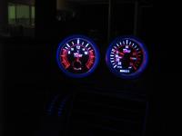
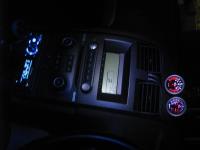
Hi all, Just thought id share my experience installing a boost gauge anda voltmeter in my 2004 BA xr6 turbo. Now only upto a few days ago I knew next to nothing about installing gauges, or car electrics and lets face it I was scared to even do anything to my car in case I broke something, but the information on this site is great. Now for a couple years I have been planning on installing some gauges though didnt want to spend a fortune, and was wanted to get my mechanic to install them, though I thought Id give it a go. I decided to go with the Xcite twin pod mounts I got off eBay for $140 delivered, then I decided to go with "Elegant - boost gauge, smoke lens, 52mm" off eBay for $27 delivered and a "Elegant - voltmeter, smoke lens, 52mm" for $22 delivered, both from eBay seller "day_long365" from Hong Kong. I always was gonna get a boost gauge but didnt know what else, saw many posts on how useless AFR gauges are and decided to go for the voltmenter considering it would be the easiest. Now I wasnt sure about getting such cheap gauges from eBay, and from Hong Kong, but for that price I though id give it a go. So the total of my purchase came to $189. Now when I got my gauges I looked at all sorts of posts to see how to hook them up and got confused a bit, in the end I couldnt see the harm of using my head units power ( I have installed a pioneer that it where the tissue box holder was and cig lighter) and ground to make it work, lucky I also bought a multimeter cheap off eBay which was essential. So to remove the ICC I used a manual I downloaded online, but was that easy that I really didnt need it. So to connect power and ground I sourced it from the head unit, and ran them up behind the ICC. Now for the voltmeter to work it requires 2 lots of 12V and 2 lots of ground source (one for the lights and one to measure the voltage, and the boost gauge requires one lot of each (for the light), then of course the pipe for boost. So to wire this up I simply wired the positive wire and the ground wire from the head unit to the back of the voltmeter, for the lights to the voltmeter I ran 2 small wires to the same +ve and -ve inlets on the same gauge (I figured whether its for the lights or to measure the volts, why cant it all come from the same source, it worked anyway) from where the head unit source came from. And then for the lights for the boost gauge I ran 2 wires again straight to the voltmeter. Now I dont know too much about circuits but couldnt understand why it couldnt work. luckily it all worked and looks pretty good. I only installed it today, but havent got a chance to hook up the boost pipe yet. Of course the only thing is that they have no dimming function, which didnt bother me anyway. Now if there is something wrong about this wiring setup someone could shed some light, but all seems to work fine. So all up I spent $189 and took about 3 hours to install myself (not too bad I thought considering I had never pulled out the ICC before or done any work on my car by myself. I will look at installing the boost pipe next weekend, is there anything I have to consider before jsut cutting the pipe from my BOV and whacking the T-peice in there? I have an APS Phase 3 kit installed and dont wanna wreck anything or effect the system at all. Anyway here is a couple of pics to show, not bad for the price of it. Will probably look at pulling the gauges apart to get the backlight blue at some stage. This info probably isnt new but thought id share my experience, and tell all that it isnt that hard to get a decent looking setup, even if you dont know too much or have a limited budget. Cheers